Redefining the cInformation Technology industry with innovative solutions, cuttin-edge technology and sustainable practices
The generic cabling system serves as the information transmission system within a building or a complex of buildings. It interconnects voice and data communication equipment, switching equipment, information management systems, equipment control systems, and security systems, while also linking these devices to external communication networks. It encompasses all cabling components associated with the connections from buildings to external networks or telephone office lines, as well as the cables between voice/data terminals in work areas and the corresponding cabling accessories.
This cabling system consists of a diverse range of components, including transmission media, line management hardware, connectors, sockets, plugs, adapters, transmission electronic circuits, electrical protection equipment, and supporting hardware.
As the physical layer of telephone networks and computer networks, the layout of the generic cabling system must fully accommodate the requirements of application networks in the coming years. In other words, its layout should be forward-looking beyond the current application architecture, forming a flexibly adjustable system structure that remains fundamentally adaptable to diverse computer network architectures.
In accordance with the Structured Cabling System standard (EIA/TIA 568B 2002) formulated by the Electronic Industries Alliance (EIA) and the Telecommunications Industry Association (TIA) of the United States, the structured cabling system is composed of six independent subsystems: the Work Area Subsystem, Horizontal Cabling Subsystem, Backbone (Vertical) Cabling Subsystem, Equipment Room Subsystem, Administration Subsystem, and Campus Backbone Subsystem. Each subsystem functions as an independent unit, and modifications to any single subsystem will not exert impacts on the others.
The Work Area Subsystem is composed of the equipment connecting terminal devices within work areas (for individual users) to information outlets, including information outlets, patch cords, adapters, and other related components.
The Horizontal Cabling Subsystem is deployed on the same floor, with one end connected to information outlets and the other terminated at the patch panels in the floor telecommunications room. Its core function is to extend the lines of the Backbone Cabling Subsystem to user areas. This subsystem primarily adopts 4-pair Unshielded Twisted Pair (UTP) cables, which can support most modern communication equipment. For scenarios requiring broadband transmission, the "fiber to the desk" solution can be implemented.
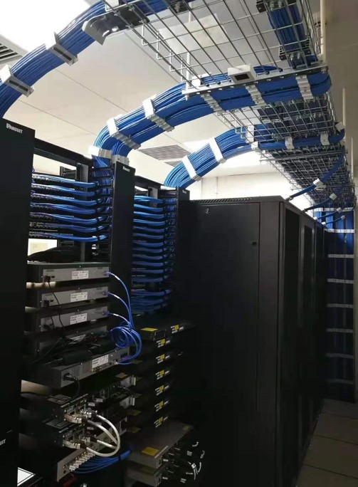
Acting as a bridge between the Backbone Cabling Subsystem and the Horizontal Cabling Subsystem, the Administration Subsystem also provides conditions for floor-level network networking. It includes twisted pair patch panels and patch cords (divided into fast-connect patch cords and conventional patch cords). For cabling systems with optical fiber requirements, optical fiber patch panels and optical fiber patch cords are also applied. When the location of terminal devices or the structure of the local area network changes, such adjustments can often be realized by modifying the patch cord connections without rewiring. Therefore, this subsystem is responsible for managing the connection of horizontal cabling on each floor to the corresponding network.
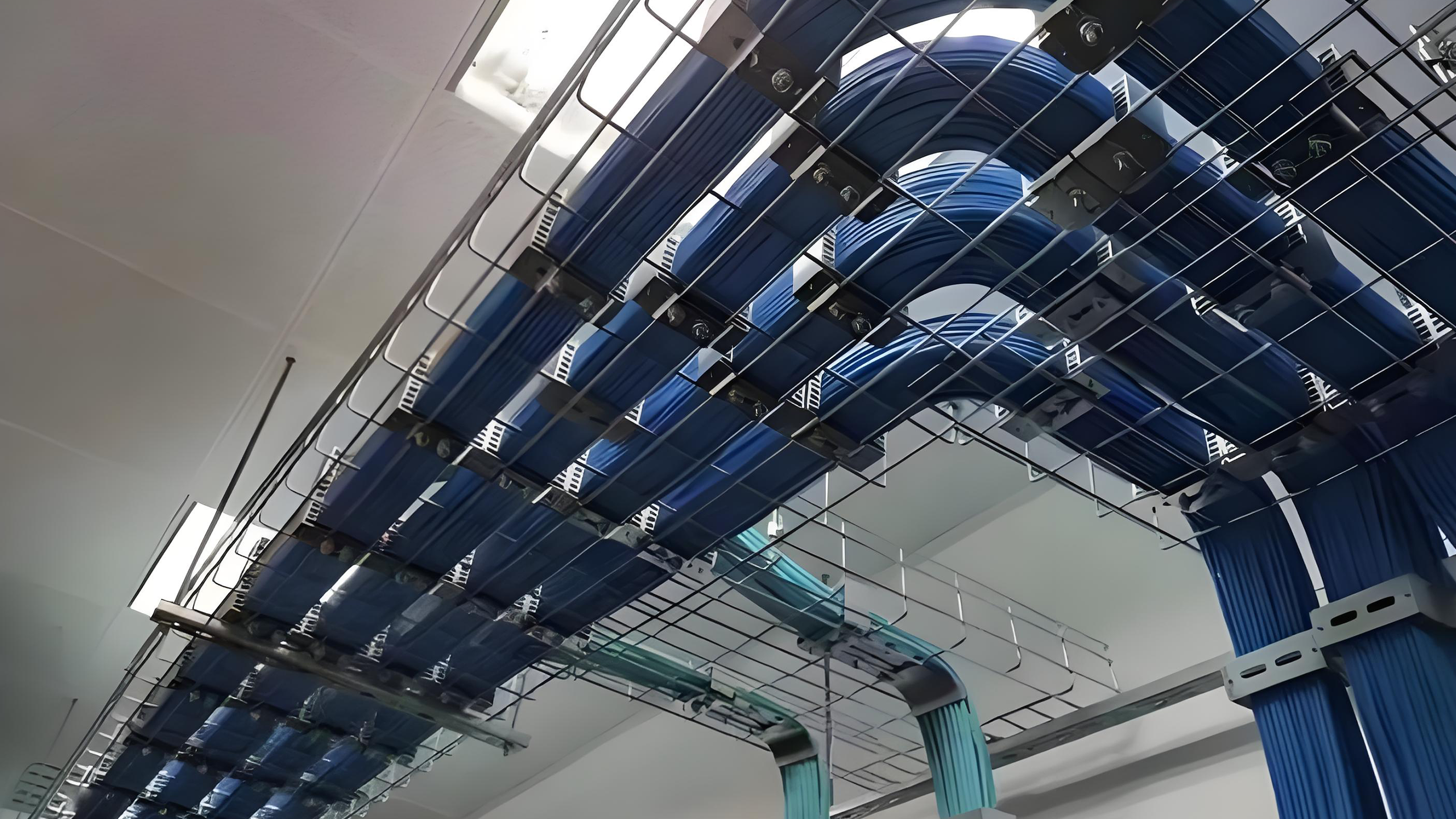
Typically, the Backbone Cabling Subsystem runs from the equipment room of a single building to the telecommunications closets on each floor, adopting large-count cables or optical fiber cables. Both ends of the cables are terminated at the patch panels in the equipment room, providing backbone cable routing for the entire building.
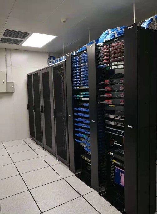
The Equipment Room Subsystem connects host computers and network equipment via cross-connect patch panels. It consists of cables in the equipment room, connecting patch panels, relevant supporting hardware, lightning protection devices, and other components. As the central unit of the entire cabling system, the rationality of its cable layout, equipment selection, and environmental condition design directly affects the normal operation, maintenance, and usage flexibility of the future information system.
The Campus Backbone Subsystem is designed to realize the interconnection of cabling systems between multiple buildings in a campus or building complex, relying on outdoor transmission media and supporting hardware to build a unified backbone transmission channel for the entire building complex, ensuring stable and efficient information transmission across buildings.